
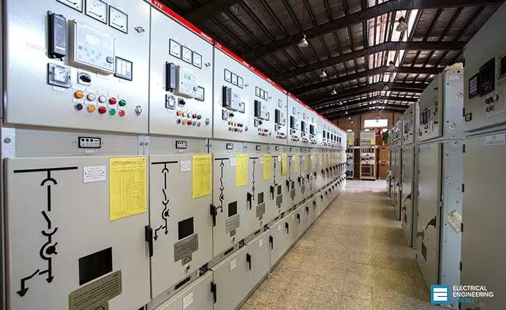
Primary Medium Voltage Switchgear (MV Switchgear)
Perfect Solution Contracting provides integrated Primary Medium Voltage (MV) Switchgear solutions for the safe distribution, switching, isolation, protection, control, and monitoring of medium-voltage electrical networks in commercial, industrial, infrastructure, utility, data center, and critical-facility projects.
Primary MV switchgear forms an important part of the electrical distribution system between the incoming utility or generation source and downstream transformers, substations, motors, feeders, and other medium-voltage loads.
Our scope can include engineering coordination, technical and material submittals, switchgear supply, installation, MV cable connections, control and auxiliary wiring, earthing, protection coordination, inspection, testing, commissioning, and final handover according to approved project requirements.
Switchgear configuration is selected according to the system nominal voltage, rated current, short-circuit level, network configuration, number of incoming and outgoing feeders, protection philosophy, operational requirements, environmental conditions, and approved electrical design.
Primary MV switchgear can be configured for applications such as utility incomers, transformer feeders, bus couplers, generator interfaces, medium-voltage motor feeders, capacitor or reactive-power equipment where applicable, and other MV distribution functions specified by the project.
Vacuum Circuit Breakers (VCB) are commonly used in modern medium-voltage switchgear for switching and fault interruption. Breaker ratings are selected according to the system voltage, normal load current, prospective fault current, and required operating duty.
Circuit breakers can be arranged as fixed or withdrawable units depending on the switchgear design and project requirements. Withdrawable configurations can provide defined connected, test, and isolated positions where supported by the selected assembly.
Protection relays are used to detect abnormal electrical conditions and initiate the required circuit-breaker operation according to the approved protection philosophy.
Protection functions can include overcurrent, earth-fault, directional, differential, under-voltage, over-voltage, frequency, transformer protection, and other functions depending on the protected feeder, equipment, network arrangement, and approved protection study.
Protection settings should be developed and coordinated with upstream and downstream protective devices to achieve the required system protection and selectivity according to the approved protection coordination study.
Current Transformers (CTs) are selected according to the required metering and protection functions, rated current, ratio, burden, accuracy class, and other technical requirements of the connected devices.
Voltage Transformers (VTs) or potential transformers can be incorporated where required for voltage measurement, protection, synchronization, metering, and other control or monitoring functions.
The main busbar system is selected according to rated current, short-circuit withstand requirements, temperature-rise limitations, switchgear arrangement, and the approved manufacturer's design.
Busbar configurations can include single-bus arrangements, sectionalized bus systems, and bus couplers according to the required electrical distribution architecture and operational philosophy.
The short-time withstand current and peak withstand capability of the switchgear should be appropriate for the prospective short-circuit level at the installation point as established by the approved electrical short-circuit study.
Primary MV switchgear incorporates mechanical and/or electrical interlocking arrangements as required by the selected design to help prevent unsafe or unintended operating sequences.
Interlocks can coordinate the operation of circuit breakers, disconnectors, earthing switches, doors, shutters, and other components according to the switchgear design and approved operating philosophy.
Earthing switches can be incorporated where required to provide an approved means of earthing isolated sections or cable circuits. Their operation is coordinated with the switchgear interlocking system.
Medium-voltage cable compartments are coordinated with the number, size, type, bending radius, and termination requirements of the incoming and outgoing MV cables.
MV cable terminations are selected according to the cable construction, insulation type, conductor size, equipment interface, system voltage, and manufacturer requirements.
Proper preparation of medium-voltage cable insulation, screens, stress-control components, and termination interfaces is critical during installation and should be performed using approved materials, procedures, and appropriately qualified personnel.
Switchgear can incorporate multifunction meters, protection relay displays, indication lamps, control switches, mimic diagrams, annunciation, and other monitoring and control devices according to the approved design.
Where specified, MV switchgear can interface with supervisory systems such as an Electrical Power Monitoring System (EPMS), SCADA, or Building Management System (BMS) for the required monitoring, status, alarm, and permitted control functions.
Communication interfaces can be provided through compatible intelligent electronic devices and the approved project communication architecture. The protocol and data points depend on the selected equipment and system integration requirements.
Control power and auxiliary supplies are coordinated with the switchgear operating philosophy. Depending on the design, auxiliary systems can include AC or DC control supplies, battery-backed DC systems, trip and close circuits, and associated supervision.
The switchgear enclosure and environmental protection are selected according to the installation location, service conditions, project specification, and manufacturer's tested assembly configuration.
Internal Arc Classification (IAC) can be specified where required by the project. Any internal-arc rating, accessibility classification, and installation conditions should correspond to the tested switchgear design and its applicable certification.
Internal-arc performance should not be assumed solely from the general switchgear type. Room arrangement, pressure-relief provisions, installation clearances, accessibility classification, and manufacturer instructions can be relevant to the complete installation.
Switchgear room coordination includes equipment dimensions, access routes, maintenance clearances, cable entry arrangements, ventilation requirements, pressure-relief provisions where applicable, and safe access for installation and operation.
The switchgear lineup is coordinated with the facility earthing system. Earthing arrangements can include a main earth bar, equipment bonding, cable screen connections, and other connections required by the approved electrical design.
Each panel, circuit breaker, feeder, protection relay, control device, and cable circuit should be clearly identified according to the approved equipment numbering and labeling system.
Before manufacturing and supply, technical documentation can include Single Line Diagrams (SLD), General Arrangement (GA) drawings, protection diagrams, control schematics, wiring diagrams, interlocking logic, component data, and equipment schedules.
Protection relay settings and associated logic are coordinated with the approved protection study and system operating philosophy before final commissioning.
Where required by the project, Factory Acceptance Testing (FAT) can be performed before shipment to verify the switchgear construction, components, wiring, mechanical operation, interlocks, protection, indications, control functions, and specified electrical tests.
FAT activities are performed according to the approved inspection and test plan, project requirements, manufacturer's procedures, and applicable requirements for the selected switchgear.
After delivery, the switchgear is inspected for shipping condition, completeness, correct assembly, alignment, mechanical installation, connections, earthing, and other installation requirements before energization.
Site testing can include insulation tests, circuit breaker mechanical and electrical operation, contact-resistance measurement where required, CT and VT verification, protection relay testing, secondary injection, interlock verification, control circuit checks, and other tests specified by the approved commissioning procedure.
Medium-voltage cable testing is performed according to the cable type, system voltage, manufacturer requirements, project specification, and approved test procedure. A single test method or voltage should not be assumed for every MV cable system.
Functional testing verifies breaker operation, protection trips, indications, alarms, local and remote controls where applicable, interlocking logic, and communication interfaces before energization.
Where required, Site Acceptance Testing (SAT) can be performed to verify the installed switchgear and its interfaces with transformers, cables, protection systems, control systems, and other associated equipment.
Energization is carried out only after completion of the required inspections, testing, protection verification, approved commissioning procedures, and relevant project authorization.
Primary Medium Voltage Switchgear is selected, manufactured, installed, and tested according to the approved project specifications, applicable utility requirements, manufacturer requirements, and relevant standards for the selected equipment.
Depending on the equipment and project requirements, relevant standards can include the IEC 62271 series for high-voltage switchgear and controlgear, including requirements applicable to the selected medium-voltage metal-enclosed switchgear and its components.
Perfect Solution Contracting provides complete Primary Medium Voltage Switchgear solutions covering engineering coordination, technical submittals, procurement, installation, MV cable terminations, control and auxiliary wiring, protection coordination, earthing, FAT/SAT support where required, testing, commissioning, and final handover according to project requirements.
- Primary Medium Voltage Switchgear.
- Vacuum Circuit Breakers (VCB).
- Incoming and outgoing MV feeders.
- Transformer feeders.
- Bus couplers and bus sectionalization.
- Main MV busbars.
- Short-circuit withstand coordination.
- Numerical protection relays.
- Overcurrent and earth-fault protection.
- Additional protection functions where required.
- Current Transformers (CTs).
- Voltage Transformers (VTs).
- Metering and monitoring.
- Mechanical and electrical interlocks.
- Earthing switches.
- MV cable compartments.
- MV cable terminations.
- Switchgear earthing and bonding.
- EPMS / SCADA / BMS interfaces where specified.
- Internal Arc Classification (IAC) where specified.
- Single Line Diagrams (SLD).
- General Arrangement (GA) drawings.
- Protection and control schematics.
- Protection relay settings and coordination.
- Factory Acceptance Testing (FAT) where required.
- Site Acceptance Testing (SAT) where required.
- Protection relay and secondary injection testing.
- Interlock and functional testing.
- Testing, commissioning, and energization support.
- Final documentation and handover.